|
Series CT Automatic Test System Highlights |
|
Traceability to international standards
Accuracy is traceable to the National Research Council of Canada. A calibration certificate is on file. A certified CT is supplied with the test system. This certified CT is used as a transfer standard. The transfer standard should be tested periodically and the system test data compared to the transfer standard calibration data. Certification software is included to calibrate the test system if necessary to assure compliance with the transfer standard data. The certification of the transfer standard may be updated by the user if required.
Data Archiving
When the data save function is enabled, all CT identification data, test result data and all test program data are saved on disk at the conclusion of each completed test sequence. The data are saved in CSV format so each data line is a record of one RCF and Phase test. This data is saved in the CT Saved Data folder. One file is opened for each date, and records are appended to the file as the day progresses. The user can retrieve data externally by network or add Microsoft Access or Excel for local use.
Remote Programming
Test program data is saved in the CT Test Program Data folder. One file is opened for each CT; the file name is the CT part number. The program data is saved as ASCII text strings separated by CReturn‘s. Test program data files may be added or edited off line with a network connection. If this is planned, the user should verify any external test programs in advance, as the system will trap any illegal or ambiguous text, display error messages and prevent its use until corrected.
|
|
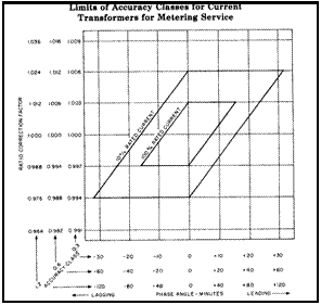
The ANSI Parallelogram (Phase Limits per ANSI C57.14)
If ANSI accuracy classes of 0.3, 0.6 or 1.2% are programmed, and if the Test Level is 100% or 10% then the phase limit data fields will display “ANSI”’. In this case, the High and Low Phase limits will be automatically calculated at test time according to the table below. This table is specified in ANSI C57.13.
If the programmer replaces the phase limit display of “ANSI” with a numeric value, then the value will be used as the phase limit and the auto limit calculation disabled.
Since the auto phase limits are derived from the actual RCF measurement, auto phase limit calculations will be done during the test cycle, after the measurement, but before the PASS/FAIL comparison. If the RCF measurement is over either RCF limit, the phase limits will be automatically set to the phase values in the table corresponding to the maximum RCF limit. |
